8085 Microprocessor-Based Stepper Motor Control System | Stepper Motor Control Using 8085 Microprocessor
• The motor is controlled by ON/OFF the control winding.
• The popular stepper motor used for demonstration in laboratories has a step size of 1.8° (i.e.,
200 steps per revolution).
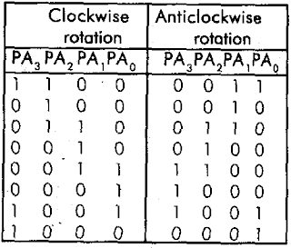
• This motor consists of four stator winding and require four switching sequence as shown.
• The basic step size of the motor is called the full step.
• By altering the switching sequence, the motor can be made to run with the incremental motion of half the full-step value. The switching sequence for half-step rotation is shown.


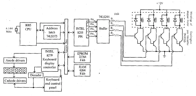
ding stepper motor is shown. The system consists of an 8085 microprocessor as CPU, EPROM, and RAM memory for program & data storage and for the stack.

• Using INTEL 8279, a keyboard and six 7-segment LED displays have been interfaced in the system. Through the keyboard, the operator can issue commands to control the system. The LED display has been provided to display messages to the operator.
• The windings of the stepper motor are connected to the collector of Darlington pair transistors.
• The transistors are switched ON/OFF by the microprocessor through the ports of 8255 and buffer (74LS245).
• A freewheeling diode is connected across each winding for fast switching.
• The flowchart for the operational flow of the stepper motor control system is shown.
• The processor has to output a switching sequence and wait for I to 5 mull-seconds before sending the next switching sequence. (The delay is necessary to allow the motor transients to die- out).

Interfacing Stepper Motor with 8085
Stepper motor is an electromechanical device that rotates through fixed angular steps when digital inputs are applied. It is suitable for precise position, speed and direction control which are required in automation system.
The angle through which stepper motor rotates with a fixed angle for each digital data is called step angle.
Different stepper motor has different step angle. The more frequently used stepper motor has step angle of 0.9 degrees and 1.8 degrees.
Depending on the sequence applied to stepper motor, it can be classified in two category:
1. 4- Step sequence or full step sequence
2. 8- Step sequence or half step sequence
Calculations:
Ex: = 200 steps are required to complete one rotation
Ex: = 50 repetition of sequence = (32) in Hexadecimal.
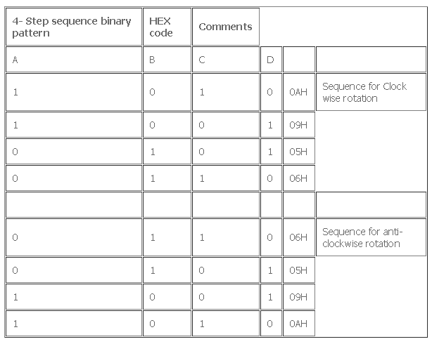
4-Step sequence:
In this type of functioning, the following 4 binary sequence/code are used for rotation: (Considering step angle= 1.8 degrees)

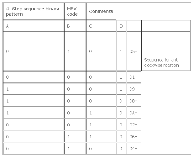
8-Step Sequence:
In this type of functioning, the following 8 binary sequence/code are used for rotation: (Considering step angle= 0.9degrees)

Chips select Logic:

Control word Format:

=80H
Program:

In the above program in the look-up table if the 4-step sequence for clock wise then the stepper motor will rotate in a clockwise direction and if the 4-step sequence for anti-clock anti-clockwise then the stepper motor will rotate in the anti-clockwise direction.
Speed control of the stepper motor is achieved by writing a program to rotate the stepper motor continuously in a delay program. We can change the delay between two steps and thus change the speed of the stepper motor.
Interfacing diagram of Stepper motor with 8085

FAQ:
Q.1 What is interfacing of stepper motor with 8085 microprocessor?
Interfacing a stepper motor with an 8085 microprocessor involves connecting the microprocessor to the stepper motor in a way that allows the microprocessor to control the motor’s movement. Here’s a simplified explanation of how this is done:
A stepper motor is a type of motor that moves in precise increments or steps, making it suitable for applications where precise control of movement is required, such as in robotics, CNC machines, and printers.
To interface a stepper motor with an 8085 microprocessor, you typically need the following components:
- Stepper Motor: This is the motor you want to control. Stepper motors come in various types and sizes, but they all have a similar basic functionality of moving in discrete steps.
- Stepper Motor Driver: A stepper motor driver is an electronic circuit that takes signals from the microprocessor and converts them into the necessary power and control signals for the stepper motor. It ensures that the motor moves accurately and in the desired direction.
- 8085 Microprocessor: This is the central processing unit that controls the stepper motor. It sends signals to the stepper motor driver to make the motor move.
- Interface Circuit: This circuit connects the microprocessor to the stepper motor driver, allowing them to communicate effectively.
Here’s a simplified step-by-step process of interfacing:
- Connect the Stepper Motor to the Driver: The wires from the stepper motor are connected to the appropriate terminals on the stepper motor driver. Stepper motors typically have four or more wires, and the driver ensures that the motor coils are energized correctly to make it move in steps.
- Connect the Driver to the Microprocessor: The output pins of the microprocessor that control the stepper motor driver are connected to the input pins of the driver. The microprocessor sends control signals to the driver to tell the motor when and how to step.
- Write Software: In the microprocessor’s programming, you write code to control the stepper motor. This code sends the necessary signals to the driver to make the motor move as required. You need to consider factors like the number of steps, speed, and direction of rotation.
- Execute the Program: When you run the program on the 8085 microprocessor, it sends signals to the driver, which, in turn, controls the stepper motor to move as specified in your program.
By interfacing the stepper motor with the 8085 microprocessor, you can precisely control the motor’s movement for various applications, such as positioning, rotation, or any other task that requires accurate control of motion.
Q.2 How to interface stepper motor with microprocessor?
To interface a stepper motor with a microprocessor:
- Connect the stepper motor to a stepper motor driver.
- Connect the driver to the microprocessor.
- Write code in the microprocessor to control the motor’s movement by sending signals to the driver.
Q.3 What is stepper motor interfacing?
Stepper motor interfacing refers to the process of connecting and controlling a stepper motor with a microcontroller or microprocessor. It involves establishing the electrical connections between the microcontroller, stepper motor, and any necessary driver circuitry, as well as writing software or code to command the motor’s movement.
The key aspects of stepper motor interfacing include:
- Electrical Connections: Establishing the physical connections between the stepper motor, motor driver, and microcontroller. This includes connecting power supplies, ground, control signals (such as step and direction), and motor coil wires.
- Motor Driver: Using a motor driver or controller circuit to amplify and control the current supplied to the stepper motor coils. The driver interprets control signals from the microcontroller and translates them into the proper current levels to drive the motor.
- Control Signals: Configuring the microcontroller to generate control signals (e.g., pulses for stepping and direction) to control the stepper motor’s movement. These signals determine the number of steps, speed, and direction of rotation.
- Programming: Writing software or code in the microcontroller to execute specific tasks or movements using the stepper motor. This code typically includes algorithms to control the motor’s position or rotation based on user or system requirements.
- Feedback: In some applications, incorporating feedback mechanisms, such as encoders or sensors, to provide information about the motor’s actual position and enable closed-loop control for enhanced accuracy and reliability.
Stepper motor interfacing is commonly used in various applications, such as robotics, CNC machines, 3D printers, and automated systems, where precise control of movement and positioning is essential. The specific details of interfacing can vary depending on the microcontroller, motor type, and application requirements.

