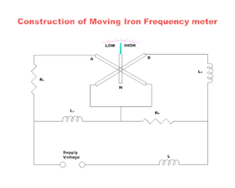
Moving Iron Frequency Meter
Moving iron frequency meters are the meters in which the two coils are fixed and a moving iron is attached to the spindle. These moving iron frequency meters depend on the following working principle.
Working Principle
This meter depends on the variations in an electric current drawn by inductive and non-inductive circuits connected in parallel. The current flows from these circuits when the frequency changes its value.
Construction

This meter consists of two fixed coils A and B whose magnetic axes are perpendicular or each other. A long and soft iron needle in pivoted at their centers. This circuit remains balanced at the supply frequency to be measured. Coil A consists of a series resistance Ra and a reactance La in parallel and coil B consists of a series resistance Rb and a reactance Lb in parallel. The series inductance helps to suppress higher harmonics in the current waveform which helps to minimize the waveform errors in the indication of the instruments.
Working of Moving Iron Frequency Meter
When the supply is connected to the meter, the current pass through coils A and B, and these two coils produce opposing torques. When the supply frequency increases then the current of coil A increases and decreases in coil B. The iron needle lies more nearly to the magnetic axis of coil A. For low frequencies, the current of coil B increases and the current of the coil A decreases.
Range
These instruments are designed to measure large amounts of frequency and also for measuring very small amounts.
The frequency range of moving iron is 0 to 125 Hz.

