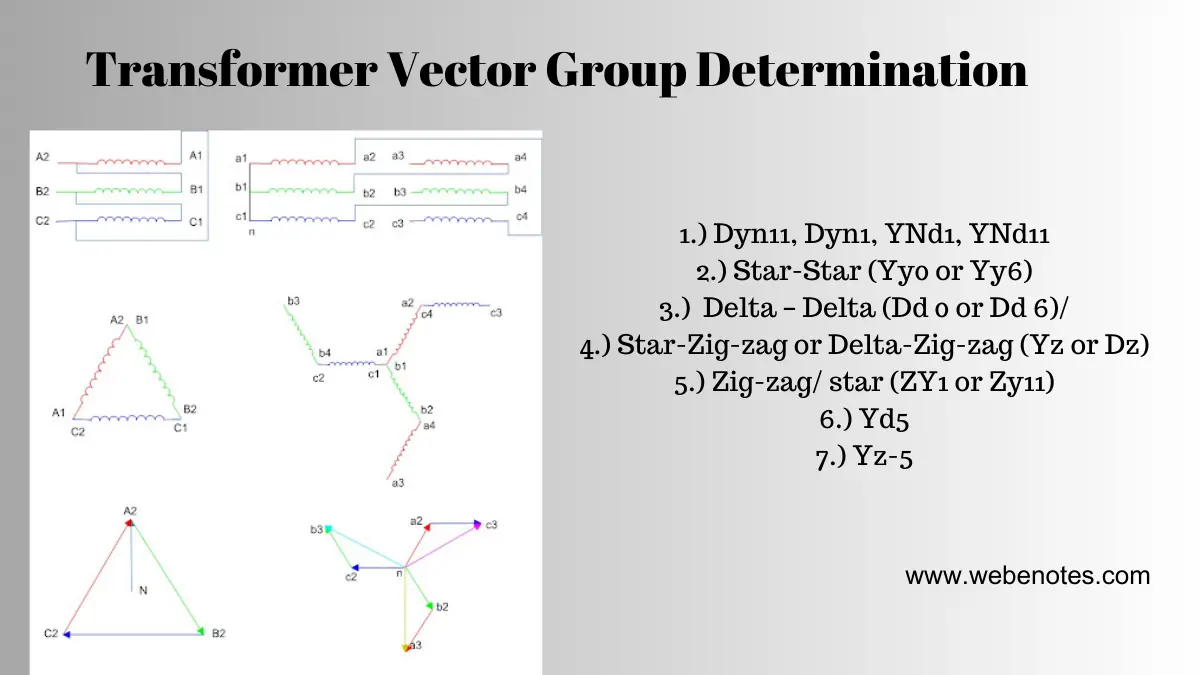
Transformer Vector Group
Determination of the transformer vector group is very essential before installing it for service. Transformer vector group connections are made based on the winding polarity. But after the winding connection is made it is necessary to check if the desired vector group has been achieved. So let us see how the tests are carried out.
We shall discuss a few vector groups, the rest you can derive in line with this article.
We shall only discuss the most common vector group of Ynyn0, Dd0, Dzn0, Ynd11, Dyn11, Ynzn11, Ynd1,Dyn1, Ynzn1, Ynyn6,Dd6, Dzn6.
However, in this article, we shall check Ynyn0, Yn,yn6, Dyn1, and Dyn11.
So let us start with the Ynyn vector group.
Ynyn:
If a transformer has both winding star connected then there is two possible vector group.
Ynyn0 or Ynyn6.
Say we have a transformer of rating 11/0.433 kV. So its H.V side per phase voltage shall be 11/1.732= 6.35 kV, and its L. V side per phase voltage shall be 0.433/1.732= 0.25 kV(no load voltage)
Terminals of the transformer are 1U, 1V, 1W, 1N for HV winding and 2U, 2V, 2W, 2N for LV winding.
Now connect the neutral point of the two Transformer, and apply three-phase voltage (at a very reduced magnitude) to the H.V winding.
MEASUREMENT AND OBSERVATION:
We shall measure voltage between 1U & 1N to know the value of applied phase voltage. then we shall measure voltage of 1U,2U and 2U,2N.
So from the image, we can see if the transformer has a vector group of Ynyn0 then the voltage between 1U and 2U shall be the difference of H.V & L.V phase voltage.
That is
V(1U,2U)=V(1U,1N)-V(2U,2N)
Where V(1U,1N) is the voltage between terminal 1U, and 1N i.e. the applied phase voltage.
So, if we get the result above then the transformer is a Ynyn0 transformer.
But for the Ynyn6 vector group, the equation shall be
V(1U,2U)=V(1U,1N)+V(2U,2N)
So if the voltage between 1U and 2U is the sum of the two-phase voltage then the transformer has a Ynyn6 vector group.
Similar checking may be done for the other two phases.
So by this method, we can identify the vector groups of the star transformer.
Now we shall look at the delta star transformer.
Dyn:
Delta star transformer has two vector groups, Dyn1 and Dyn11.
Now let us see how we can identify the groups.
First, we have to short-circuit terminals 1U and 2U. If these terminals are shorted and a reduced voltage is applied to the transformer then the resultant vector group will be either one of the below.
So from the above picture, we can understand what the vector group of the transformer shall look like.
Now we will measure a few voltages and observe the relationship between them.
MEASUREMENT AND OBSERVATION:
If the transformer has a vector group of Dyn11 then the following relationship shall be applicable.
1. V(1U,1V)=V(1V,2N)+V(2U,2N)
2. V(1V,2W)=V(1V,2V)
and
3. V(1W,2V)>V(1W,2W)
So we shall measure the terminal voltage as shown and check the relationship. If the we found the above relationship then we can conclude that the transformer has a vector group of Dyn11
For Dyn1 the relationship shall be slightly different
1. V(1U,1W)=V(1W,2N)+V(2U,2N)
2. V(1W,2W)=V(1W,2V)
and
3. V(1V,2W)>V(1V,2V)
So by checking this relationship we can determine the vector group of a delta star transformer.
For other vector groups, the testing procedure shall be similar to mentioned

